We provide

onsemi is the industry leader in conversions of FPGAs to ASICs. We provide significant cost savings, performance enhancement, and product assurance. Our customers have been able to reduce system costs considerably by successfully substituting their high cost FPGAs with drop-in ASIC replacements in over 5,000 applications. In most cases, higher performance, lower power, better thermal performance, and improved radiation immunity can be achieved in the ASIC.


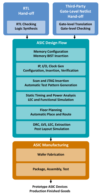
FPGA Flow Diagram
FPGA Flow Diagram

Why Convert?

onsemi has successfully converted thousands of designs from costly FPGAs to efficient ASICs throughout the past few decades. The lower unit cost of an ASIC has long been a key motivating factor in such conversions. However, the appeal of FPGA to ASIC conversions goes far beyond the cost savings. The significant power savings realized through using an ASIC in place of an FPGA significantly increases battery life. In contrast to the programmable logic used in FPGAs, the hard-coding of the logic in an ASIC does not allow reprogramming of the device, thereby increasing security and reliability. This added reliability makes ASICs the obvious choice for flight-critical applications where SRAM based FPGAs are typically not qualified.

onsemi provides a parallel development path for FPGA development. This leverages the inherent flexibility of an FPGA during the development phase while accelerating the path to low-cost production with an ASIC. onsemi offers competitive design cycle times, allowing for a quick ramp to production. We also maintain manufacturing processes for long periods of time to help ensure an uninterrupted supply.

Conversion Reference Manual
FPGA Design Flow
FPGA Design Flow
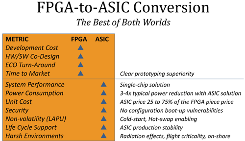
FPGA-to-ASIC Conversion

Features

FPGAs use leading edge technologies in order to obtain the same system performance as an ASIC in older technologies. A design implemented in an FPGA will have a larger die size due to the architecture and fabric, and due to the programmable logic and interconnect overhead.

This not only increases the overall power used in the FPGA but has a direct effect on the cost. For the same amount of gates and RAM, an ASIC has a much smaller die size, and usually requires fewer levels of metal. This is due to more efficient custom routing used in an ASIC.

The smaller die size, fewer processing steps, and older generation of technology are the main cost advantages for the ASIC. By taking advantage of the superior density offered by an ASIC and possibly combining several FPGAs onto a single chip, additional benefits can be realized: reduced board size, smaller BOM, improved power consumption, and maximized cost savings.

Automatic design migration to an ASIC
Low cost drop-in replacements
Multiple FPGA-to-one conversions
Original circuit functionality and performance maintained and improved
Accept over 70 FPGA and ASIC formats

Benefits

onsemi directly owns and operates fabs, with access to industry standard third-party foundries. We have more than 25 years of conversion experience with over 5,000 designs converted to working silicon.


Single-chip, non-volatile solutions

Live-at-Power-Up (LAPU), enhanced security, immunity to configuration logic errors resulting from SEE.

Improved cost through die size reduction
Strategic alliances with package suppliers to offer complete solution
Competitive development time spans, with an emphasis on time-to-market
Long fabrication process life
On-shore production paths for most technologies
Optional performance enhancements for a competitive edge
Significant reduction in power usage

Customization Drives Higher Performance

As device speeds increase, FPGAs experience a dramatic increase in power consumption over an ASIC design. This is largely due to how FPGAs are routed. An FPGA cannot be directly routed from point A to point B on a chip. Instead, a signal must be routed through many programmable routing switches and wire segments, each with considerable capacitive overhead, which causes an increase in power consumption.

In addition, clocks are routed with predefined clock networks across the entire die, with oversized drivers to handle all potential clocking requirements. This large clock network has a sizeable capacitive load and will draw a substantial amount of power at higher frequencies.

In the ASIC, clock drivers and networks are tailored to the specific clock network requirements and routed efficiently in metal layers. There is no unused logic in ASICs drawing power. High-end FPGA technology uses smaller geometry technology than ASICs while using the same core voltage. The combination of advanced geometry technologies and same core voltage as the ASIC results in more leakage, adding to the higher power usage in FPGAs. The reduction in power usage by an ASIC allows the use of less complex packages, again helping reduce the overall cost of the product, as package costs can be a third or more of the device cost.