Efficiency and power density have become the most critical key performance indicators (KPIs) for the next generation of power electronics systems in mobility, data center infrastructure and renewable energy.
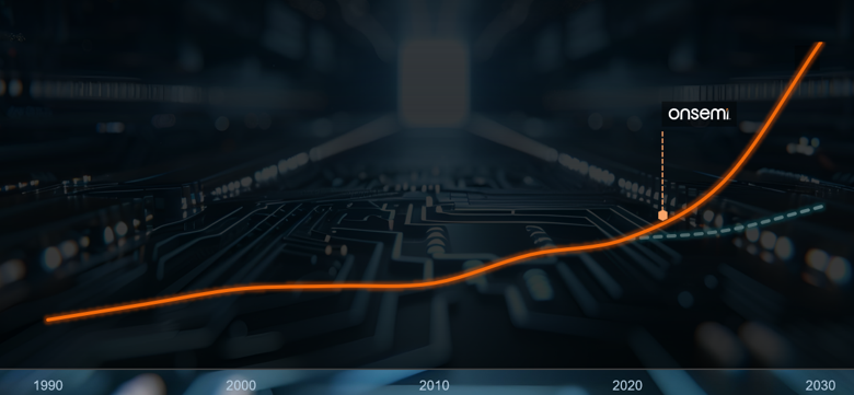
System level power density has historically increased by 10–20 % every two years, reflecting steady linear growth. However, rising energy demands in hyperscale data centers, traction systems, aerospace platforms, and emerging domains such as neurotechnology are intensifying this trajectory. Contemporary roadmaps therefore increasingly posit a shift toward exponential scaling, anticipating an effective doubling of system level power density every two years.
Modern power electronic systems comprise a tightly coupled network of power semiconductors, passive components, cooling solutions, control software, and mechanical integration. Optimizing these components independently can lead to some improvements but fails to unlock the full performance potential of the overall system.
This article outlines a system-level optimization methodology and illustrates why breaking down traditional silos between design disciplines is essential to unlock future gains, and to meet the stringent requirements of today’s most demanding and system-critical applications.
2. Drivers for System Level Optimization
2.1 Electrification and Power Demand Growth
Electrified vehicles, heat pumps, and renewable energy integration significantly increase local and global power demand. In parallel, data centers already consume several gigawatts of electrical power in individual regions, with demand rising sharply with artificial intelligence workloads. Even marginal efficiency improvements in conversion stages translate into substantial energy savings, reduced cooling requirements, and lower operational costs when deployed at scale.
At the same time, progress toward meeting regulatory and sustainability targets is measured by overall system efficiency, not isolated component improvement. This shifts the optimization focus from individual devices toward holistic energy flow across the system.
2.2 Limits of Component Level Optimization
Wide‑bandgap devices such as SiC MOSFETs and GaN HEMTs provide lower switching losses and allow higher operating frequencies compared with silicon devices. Nevertheless, their full potential cannot be realized if parasitic inductances, thermal bottlenecks, or overly conservative control strategies dominate system behavior. For example, reducing transistor switching losses may expose the DC‑link capacitor, gate‑driver dynamics, or cooling system as new limiting factors.
In such cases, optimization confined to a single component merely shifts losses within the system instead of reducing them altogether. As power density increases, these interactions become increasingly critical, reinforcing the need for system‑level design methodologies.
3. From Component Silos to System Thinking
Traditional power‑electronic design follows a hierarchical structure: semiconductor selection, packaging, cooling, passives, and control are treated as largely independent design steps. This “silo” approach simplifies project organization and responsibility allocation but inherently restricts achievable system performance.
In contrast, system‑level optimization treats the power electronic converter as an integrated electromechanical system. Electrical waveforms, thermal behavior, mechanical constraints, and control dynamics are evaluated simultaneously. This enables informed trade‑offs between competing objectives such as switching speed, electromagnetic interference (EMI), thermal cycling, efficiency at partial load, and long‑term reliability. Breaking down functional silos does not imply abandoning domain expertise. Instead, it requires structured interfaces and shared metrics that allow each discipline to contribute toward a common system objective.
3.1 Making System Optimization Tangible
In practice, system-level optimization begins with defining a shared set of performance targets across various disciplines including efficiency maps, thermal limits, cost constraints, and dynamic behavior.
A simplified traction inverter system illustrates this interaction:
- The power stage (SiC inverter) defines switching losses and dv/dt behavior
- The electric machine determines current ripple sensitivity and iron/copper losses
- The thermal system constrains allowable switching energy and current density
- The control strategy shapes switching frequency, modulation, and operating points
These elements form a tightly coupled system, where changing one parameter (e.g., switching frequency) simultaneously affects losses, EMI, thermal headroom, and even motor efficiency.
Therefore, engineers must increasingly rely on iterative system-level exploration, combining simulation, hardware evaluation, and application-specific reference designs to converge toward an optimal solution.
4. Efficiency Gains Through System Optimization
4.1 Automotive Traction Inverters as a Case Study
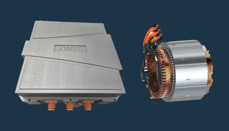
In electric vehicles, drivetrain efficiency is strongly determined by the interaction between the traction inverter and the electric machine. Optimizing both jointly yields significantly higher efficiency gains than improving the inverter alone, resulting in a driving range increase that is more than four times greater than what can be achieved through inverter-only optimization. This requires deliberately operating neither component at its individual optimum but instead aligning both toward the global optimum of the combined system.
Evaluating these trade-offs requires more than theoretical analysis. Engineers typically validate system behavior using reference inverter platforms, where semiconductor selection, layout parasitics, cooling concepts, and control strategies can be tested under realistic operating conditions.
For example, modern SiC-based traction inverter platforms enable exploration of:
- Switching frequency vs. efficiency trade-offs across drive cycles
- Interaction between inverter switching behavior and motor losses
- Impact of packaging and layout on parasitic inductance and voltage overshoot
- Thermal coupling between power modules and cooling systems under transient loads
The optimal operating point emerges from a balanced trade‑off between inverter switching behavior and the loss characteristics of the electric machine. A system-level perspective ensures that losses are minimized across both components simultaneously, rather than optimizing them in isolation.
4.2 Coordinated Electrical and Thermal Design
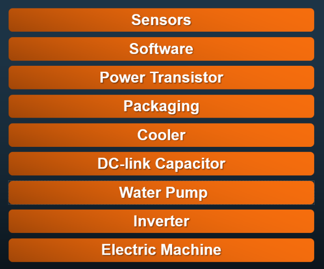
While the example in the last caption only considers two subsystems, a complete vehicle offers significantly more degrees of freedom for system‑level optimization (see Figure 3). Only by optimizing all relevant subsystems in an integrated manner can the full system performance be realized. Higher switching frequencies reduce passive‑component size and improve dynamic performance but simultaneously increase switching losses and thermal stress. Conversely, oversized cooling systems reduce junction temperatures but add volume, mass, and cost, reducing overall power density.
System‑level optimization quantifies these trade‑offs by jointly modeling electrical losses and thermal resistances. For example, a power module with near‑ideal thermal coupling to its cooler enables more aggressive switching strategies without violating junction‑temperature limits. However, the cooling system must be designed to handle transient heat flux rather than relying solely on conservative steady‑state assumptions. By treating electrical and thermal domains as interdependent rather than sequential, designers can avoid overly conservative design margins while maintaining reliability.
5. Control and Software as System‑Level Enablers
Control algorithms and embedded software increasingly define system efficiency and robustness. Adaptive modulation schemes, dynamic gate‑driver control, and operating‑point‑dependent switching strategies allow converters to maintain high efficiency across wide load ranges.
In a system‑optimized design, control software is not an afterthought but a core optimization variable. Software can compensate for hardware limitations, mitigate parasitic effects, and enable operation closer to physical limits when supported by accurate sensing and thermal models. The integration of software into system‑level optimization also enables future updates and performance improvements without hardware changes.
6. DC‑Link, Magnetics and Passive Components
Passive components are frequently the hidden bottleneck in high‑power‑density systems. DC‑link capacitors, bus structures, and magnetic components strongly influence switching behavior, EMI, and reliability. Their electrical performance cannot be separated from mechanical placement and thermal coupling.
System‑level optimization explicitly considers the interaction between switching transients, parasitic inductances, and capacitor technology. This enables reduction of voltage overshoot, improved dv/dt control, and lower overall loss. Similarly, optimized magnetic design balances copper loss, core loss, thermal dissipation, and acoustic noise within a unified framework.
7. Multidisciplinary Design and Parallel Development
One major obstacle to system‑level optimization is organizational rather than technical. Electrical, mechanical, and software engineers often operate sequentially, leading to long development cycles and sub-optimal integration.
Future power electronic systems demand parallel, multidisciplinary development where design iterations span the entire stack simultaneously. This approach shortens design cycles, exposes system‑level trade‑offs early, and avoids costly late‑stage redesigns. It also enables continuous optimization rather than fixed design freezes between stages.
8. Role of Advanced Modeling, Data, and Validation
Accurate system‑level optimization relies on high‑fidelity models that capture interactions between components. This includes:
- Electrical models with realistic parasitic elements and switching behavior
- Thermal models linking junction temperature to cooling architecture and ambient conditions
- Control models reflecting real‑time constraints, sensor accuracy, and communication delays
Increasingly, data‑driven methods and artificial‑intelligence techniques support design‑space exploration and sensitivity analysis. However, these tools complement rather than replace physical insight. Meaningful optimization requires identifying which parameters materially affect system performance and which variations are secondary.
For example, system-level power simulation tools allow designers to model inverter stages using realistic semiconductor characteristics, including switching losses, capacitances, and temperature dependencies. This enables early evaluation of:
- Efficiency across operating conditions
- Switching behavior and dv/dt limits
- Thermal interaction between devices and cooling systems
Equally important is experimental validation. System‑level optimization must be verified through targeted measurements that confirm predicted loss distributions, thermal behavior, and dynamic performance under real operating conditions.
By combining device-level models with system-level simulation environments, engineers can rapidly explore design spaces and identify optimal operating regions before validation on physical hardware.
9. Innovation Beyond Incremental Improvement
Historical breakthroughs often arise not from incremental refinement but from rethinking fundamental assumptions. The transition from silicon to wide‑bandgap semiconductors exemplifies such a paradigm shift. Likewise, future efficiency leaps may result from architectural changes—such as higher DC‑link voltages, integrated drive units, advanced cooling concepts, or software‑defined power stages—enabled by holistic system design.
Leadership in power electronics therefore requires fostering a culture that encourages cross‑disciplinary thinking, questioning established practices, and embracing controlled risk in pursuit of disruptive improvements.
10. Implications for Industry and Research
For industry, system‑level optimization translates directly into competitive advantage through higher efficiency, reduced material usage, improved reliability, and shorter time‑to‑market. For academia and research institutions, it highlights the need for integrated curricula and research programs that bridge traditional disciplinary boundaries.
Close collaboration between semiconductor manufacturers, system integrators, and end users becomes increasingly important, as many optimization potentials span organizational interfaces rather than individual components.
Conclusion
The next generation of power electronic systems will be defined not by isolated component advances but by the effectiveness of system‑level optimization. Efficiency and power‑density targets driven by electrification and sustainability goals can only be met by coordinated co‑design of semiconductors, passives, cooling systems, and control software.
By removing silo barriers, adopting multidisciplinary development approaches, and leveraging advanced modeling and data‑driven validation, the power‑electronics community can continue to drive innovation and enable the electrified future.