This blog is the second in a three part series on the topic of making accurate shunt resistor connections where the first blog discussed "Diagnosing Shunt Resistor Connection Errors".Today we are going to discuss shunt resistor design architecture and shunt resistor manufacturer’s typical recommended guidelines for connecting to their shunts. There are many incorrect ways to connect to a shunt resistor but the one and the only correct way to accurately connect a shunt resistor is to follow the shunt manufacturer’s recommended guidelines.
In Figure 1 below, take a look at the shunt resistor connection on the left labeled “Ideal.” The ideal connection uses traces that are uniform and equal in length and dimension; the traces connect to the shunt at a location that shunt manufacturers typically recommend and finally the voltage measured or sensed by the amplifier corresponds exactly to the drop across the active portion of the shunt. Now, take a moment to compare the ideal connection with the “non-ideal” connection also shown in the figure.
Figure 1: Ideal vs Non-Ideal Shunt Resistor Connections
Shunt Resistor Design
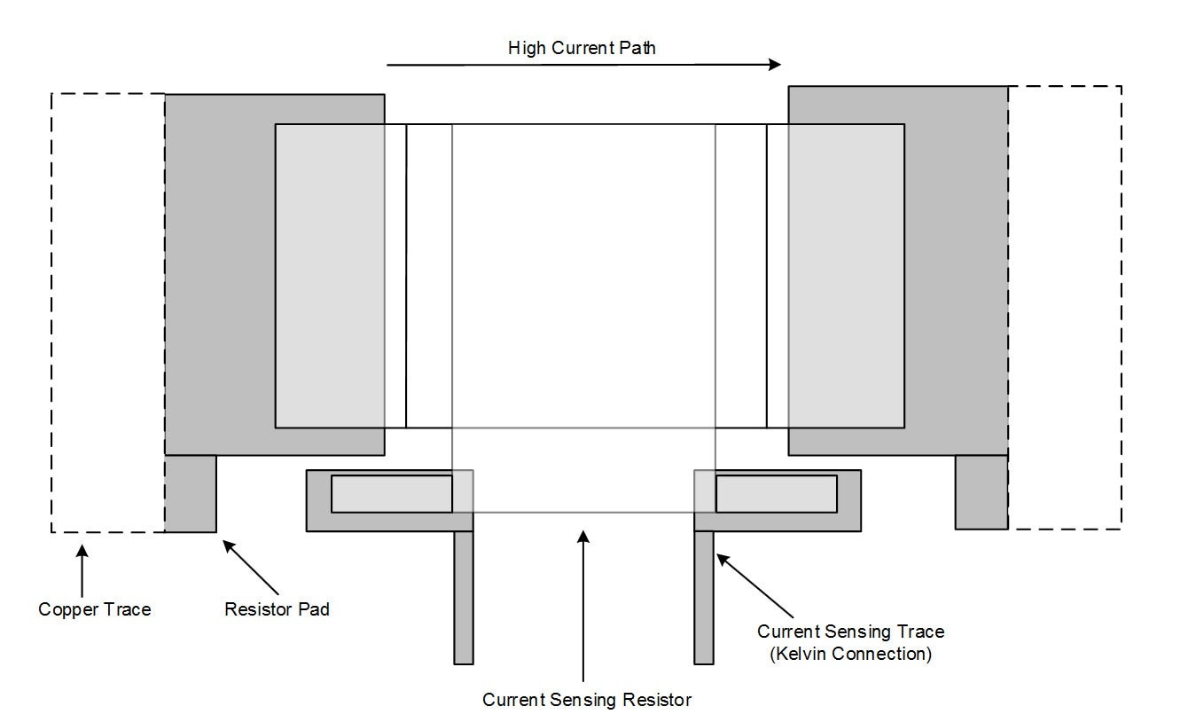
It is useful to understand the architecture of a current shunt in order to get maximum efficiency. The ends of the shunt that get soldered down are usually copper material, while the shunt itself is a different material such as manganin; it is this center section material that the shunt manufacturer is trimming to an exact value. The objective is to accurately capture the voltage drop across the resistor material itself and none of the voltage drop in the end connections. Figure 2 shows the typical manufacturer recommended connection points for a two terminal shunt resistor. The sense trace connections are in the middle of either side, right at the plane of where the shunt resistor material interfaces with the copper lead.
Figure 2: Typical Manufacturer Recommended Connection for a Two Terminal Shunt Resistor
Always follow the shunt manufacturer’s recommendations on connecting to the shunt in the event that they are different from those highlighted in Figure 2. Notice in Figure 3 that the stray lead resistance and stray sense trace resistance is depicted - an improper connection will add these unwanted stray resistances to the measurement and increase error.
Figure 3: Connection to a Two Terminal Shunt Resistor Depicting Stray Resistances (RLead and RSense)
The four terminal shunt resistor shown in Figure 4 provides a more obvious way to connect the Kelvin sense traces to the shunt while maintaining a high level of accuracy. It should be noted, however, that there is a cost penalty for a four-terminal shunt resistor.
Figure 4: Typical Manufacturer Recommended Shunt Connection for a Four Terminal Shunt Resistor
Making accurate shunt resistor connections is not difficult but it does require understanding the shunt manufacturers connection guidelines and proper PCB design to make the correct connection.
Stay tuned for part three, the final part in this blog series. In part three, we will conclude the discussion with the topic, “Good vs Bad Shunt Resistor Connections.” In this final part of our series, we will put everything together that was discussed in parts one and two, and take a look at a properly designed PCB and compare measurement data between a PCB with a good connection and a PCB with a bad connection.
For more information about out Current Sense Amplifiers here.


