When converting to electric vehicles (EVs), perhaps the biggest change for the driver is refueling. No longer does refueling mean a trip to a gas station, instead an available charging point must be located.
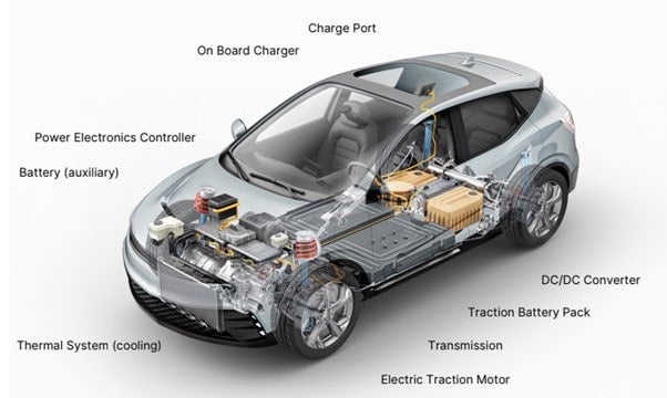
While the rollout of public chargers is growing rapidly, many prefer to charge their vehicles at home. Unlike many high-power public chargers which provide DC power that charges the battery directly, home-based chargers deliver AC power that must be converted via an on board charger (OBC) before the battery can be charged.
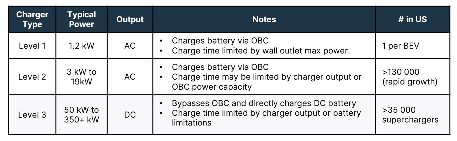
Looking at the charging infrastructure, the high-power DC charger is the fastest, but also the most expensive solution, suitable for highways and heavy commercial installations. AC chargers are much more common in light commercial, small business and residential installations. AC chargers provide a cost-effective solution that relies on the OBC inside the EV.
As EV technology evolves, so must the OBC, especially as automakers migrate from 400 V to 800 V battery architecture. Consumer demand and increasing battery capacity (kWh) are also driving factors. The desire to charge EVs more quickly is leading to OBC power capability rising from 3.6 kW in early designs up to 7.2 kW or 11 kW, provided the grid can support this.
Key Design Considerations for OBC
Before embarking on detailed design for an OBC, designers must be aware of the key design parameters as these will impact the selection of components and topology.
Determining the power level is a crucial first step, as this impacts user experience. At a simple level, the higher the power of the OBC, the shorter the time taken to deliver charge into the battery. In many cases, users charge their vehicles at home while they are otherwise occupied (or sleeping!) so this charge time is less of an issue. However, for mid-journey recharging, charge time is a very important factor. When connecting to a Level 2 charger, the OBC power rating will typically be around 7.2 or 11 kW. More powerful OBCs have a power rating of 22 kW, and in some cases even more.
The power level of the OBC is designed to match the capacity of the electrical grid and the limitations set by circuit breakers, such as maximum current. Let's take a 230 V grid as an example. A 7.2 kW OBC would draw up to 32 A in a single-phase charger design. An 11 or 22 kW OBC is optimized for a three-phase AC input and draws up to 16 A or 32 A from each phase of the AC charger. These amperages are typically the limit for the AC charger you would install to keep charging cost effective when it comes to your home or a light commercial building with 230 V. Of course, AC ports with even higher available power can be found in public spaces and heavier commercial installations, where you can take advantage of power levels above 22 kW.
With EVs being sold globally, there is the challenge that grid voltages vary around the world with 110V AC being the voltage in North America while 230V AC is the most prevalent in Europe and China. Within the power industry, it is common to design for a ‘universal input’ of 86-264V AC which would allow for a single OBC to be used, no matter where the vehicle is being shipped.
As the same charging port could be used to charge the EV from a fast roadside charger that provides DC power, it is necessary to provide a bypass feature for the DC power to flow directly into the high voltage battery as AC-DC conversion inside the OBC is not required.
Efficiency is one of the most critical parameters for an OBC. Higher efficiency means that more charge is delivered to the battery in a given time. This reduces charging time, especially when operating at the per-phase current limit of the grid.
The further an OBC moves from 100% efficiency, the more heat is generated within the unit. Not only is this wasteful, but it also requires additional cooling, which can be challenging in a modern EV due to space constraints. As size and weight are added to an OBC, making the vehicle heavier, it saps more energy from the battery when driving which will ultimately reduce the overall range of the vehicle.
Improving efficiency is on the agenda of every power designer and this is a complex and multifaceted challenge. The selection of components (particularly MOSFETs) is crucial to attaining the best efficiency, although the conversion topology and control scheme also have a significant impact.
Power Stages in OBC Design
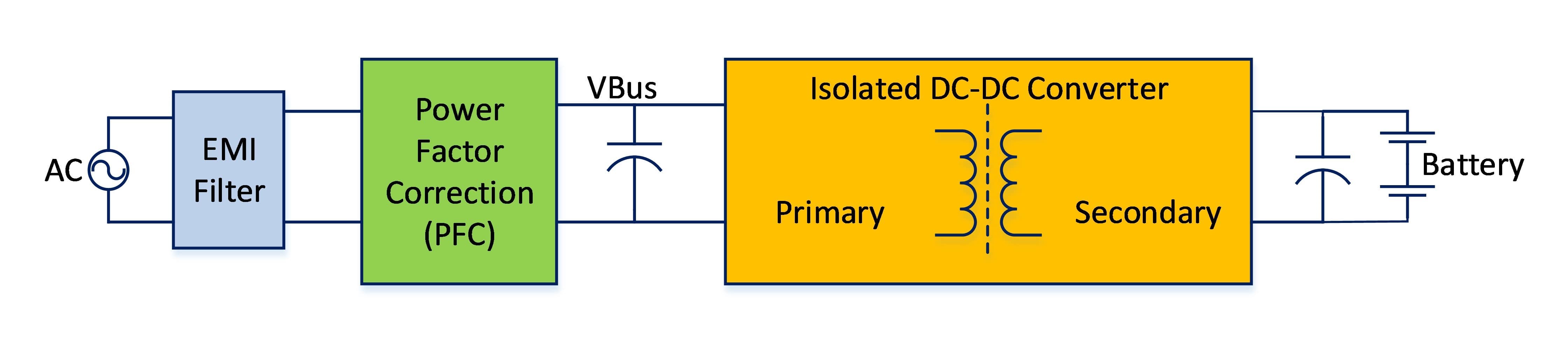
OBC consists of three main blocks, an EMI filter, a power factor correction (PFC) stage and an isolated DC-DC converter which has separate primary and secondary stages. These stages can be built using various power topologies, each offering different benefits in terms of efficiency, cost and performance.
The PFC stage is the front end of the OBC, and it performs a number of important functions. Firstly, it rectifies the incoming AC grid voltage into a DC voltage, often known as the “bus voltage.” This voltage is also regulated by the PFC stage and is often around 400V, depending on the input AC voltage from the grid.
Another important function of the PFC stage is improving the power factor as, if this is poor, then the cost of electricity may rise due to an effect known as ‘phantom power’. To do this, the PFC stage tries to keep the voltage and current waveforms in phase as well as shaping the current waveform to be as close to a pure sinusoid as possible – thereby reducing the total harmonic distortion (THD). A good PFC stage will return a power factor that is approaching unity.
The DC-DC converter has two roles, isolating the voltage coming from the grid and converting the bus voltage from the PFC stage to a voltage level suitable for charging the EV battery, whether it is a 400 V or 800 V type.
The primary stage of the DC-DC “chops” the DC bus voltage so that it can pass through a transformer between the primary and secondary stages, while the secondary stage rectifies and regulates the output voltage to a level suitable for charging the battery.
Designers have to consider whether to make the OBC unidirectional or bidirectional, as this influences the available power stage topologies and overall cost of the OBC. Adding bidirectional capability is one of the design trends for OBC, which can make your car also a large mobile battery storage.
Conclusion
Designing an efficient OBC is not a trivial exercise, especially as the size and performance is crucial to the operation of the EV and the overall customer experience. The design must be able to cope with a range of input voltages and convert kilowatts of power as efficiently as possible into a lightweight and compact footprint.
There are multiple choices of topology and control schemes to consider and a wide range of components to choose from, all of which will define the performance of the final design.
To simplify the task, many designers opt to use components from as few sources as possible and, ideally, from a single source.
onsemi offers a wide range of discrete components and power modules that can be used to design a complete OBC powertrain. The OBC system solution guide examines different power topologies and available components. Download the system solution guide and check out more info on our OBC Solution Page.
Additional resources: