In electric and hybrid-electric vehicles, a method is required to disconnect the high-voltage battery from the rest of the vehicle. Traditionally, a specially designed high current relay (contactor) has been the preferred solution to perform this function. This relay must be designed in a manner that will permit disconnection, under load, without being damaged. This is accomplished by the use of a relay with vacuum encapsulated contacts. These contactors are typically filled with an inert gas, surrounding the contacts to eliminate the presence of air. Typically, in a high voltage battery system, three of these contactors are required: one for each of the two main battery conductors and a third, smaller version, for the pre-charge function. See the conventional battery disconnect circuit diagram in Figure 1.
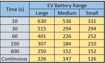
EV manufactures have long hoped for a smaller, lighter and less expensive solution, to this battery disconnecting problem. Power semiconductor solutions have often been proposed as the replacement of the contactors and will produce a compact solid-state solution. The challenges presented to the semiconductor power-switch design are also quite significant. A simple direct exchange of each of the relays with a suitable power-switch would not be a viable solution. Since in an EV battery system current can flow in both directions, the power switch must be able to conduct and block current in both directions. When the vehicle is at rest (parked vehicle), the battery off-state leakage must be extremely low to prevent discharge and potentially dangerous situations. In addition, the current levels passing through the main contactors is equal to those passing through the HV battery itself. During vehicle operations where large accelerations are required, the current levels will be very high and will last for periods that will place major challenges upon the power-switch thermal management system. Typical vehicular current levels versus operating modes are shown in Figure 2.
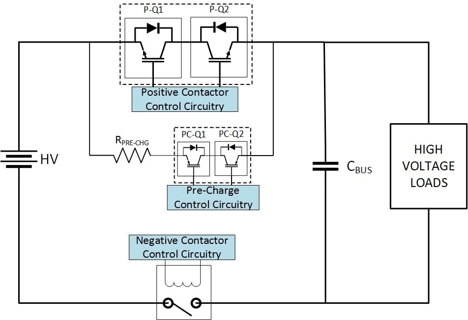
One proposed battery disconnect system solution is shown in Figure 3. It solves the bi-directional conduction issue by using multiple back-to-back IGBT devices, in parallel. These devices must be of a suitable current rating and must have an adequate thermal heatsinking system to deal with the large power loss. The off-state leakage problem is solved by maintaining a single contactor in the negative battery conductor. This is required for the complete solution to meet the parked vehicle battery leakage specification. Future applications using WBG power devices might be the technology to implement a fully solid-state solution.
A similar situation is evolving in the newly realized 48V mild hybrid vehicles. They are primarily powered by Lithium–Ion batteries which have the same requirements, as do the HV EV’s, although the current and voltage levels are considerably different. Here MOSFET modules are proposed to solve this problem. In addition, the replacement of the pre-charge hardware with a completely solid-state solution, requires some additional control circuitry that can charge the output capacitive bus, using switch mode techniques. The development of these BDU systems are new to the xEV industry and a great amount of specialized design and innovation will be required for them to be successful.


