Convenient and efficient charging
Convenient and efficient charging is critical to the success of all battery powered electric vehicles (BEV). The more places charging is available and the faster they can be charged, the more likely the buying public is to purchase a BEV over a fossil fuel vehicle.
However, designing a fast EV charger to be compact, efficient, and reliable is not a trivial exercise. Apart from the actual conversion circuit, hardware protection techniques are essential, requiring designers to analyze multiple ‘what-if’ scenarios. Solutions will include snubbers formed from passive RC networks and blocking components.
Excessive voltage and/or current is always a concern, and protection is needed to ensure that power semiconductors are not damaged. One technique is to add a voltage comparator with a defined threshold and hysteresis that blocks gate drivers if there is an overvoltage.
Over current can be more challenging, although onsemi’s NDC57000 features over-current Desaturation Protection (DESAT), thereby addressing the issue with minimal impact on the BOM and product cost.
Hardware protections such as these are of particular importance during testing and debugging, especially the bring-up phase, when unpredicted switching is most likely to occur.
NDC57000
The NDC57000 is used in the PFC stage to protect SiC Power Integrated Modules (PIMs).Testing methodology is explained to evaluate DESAT trip current thresholds which is a must prior functional testing. The DC link capacitors are used to source required high peak tripping current and a pulse is injected into the gate to turn on the modules and allow the DESAT protection to trip.
As a result of this testing, theoretical values can be compared to the practical values, and design adjustments made.
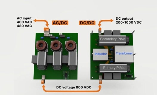
For the main Dual Active Bridge (DAB) DCDC converter, the NDC57000 is used as well, relying on voltage drops to monitor current levels. However, this approach is sensitive to device characteristics and, while datasheets contain some information, prototype verification is almost always needed.
Another approach is to perform a simulation, allowing parameters to be set more accurately, before embarking on a prototype. This allows primary and secondary short circuit effects to be simulated and understood in a non-destructive manner.A discrete enhancement of DESAT protection is presented to provide wide operating coltage range solution to designers of DCDC stage where output voltage spans as much as 200-1000V.
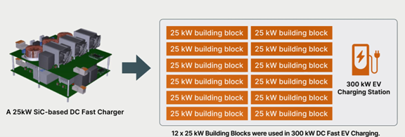
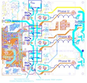
One of the significant benefits of SiC technology is its ability to operate at high frequencies. However, this implies fast dv/dt slew rates that have implications for the physical layout of the 25 kW fast charger. Layouts must be optimized to minimize parasitic inductance, especially in power traces. Also, snubber circuits are required at several points to minimize overshoots and ringing that can be damaging and produce EMI issues.
System level control is another important area and the 25 kW fast charger features multiple closed-loop controllers within the PFC and DAB to control parameters such as transformer active flux balancing and primary to secondary phase shifts to control output voltage and current. One challenge here is selecting the gain for each loop, so that the overall system cannot become unstable.
As testing requires high power equipment, often designers construct a loop-back arrangement with two PFC stages and a DAB on the bench to permit safe testing under controlled conditions. Loop-back testing is suitable also for mass production burn-in phase where energy of Device Under Test is recuperated which brings substantial manufacturing cost savings to pursue world low carbon emission mission.
onsemi has produced a technical white paper that considers in detail the challenges faced with designing and, most importantly, debugging a real-world 25 kW fast DC charging module for ultra-fast EV chargers. The paper is packed with practical tips for methods that can be used along with multiple tips and lessons that were learned during the process.
You can find onsemi’s 25 kW DC fast charger white paper here. Learn more about the 25kW SiC Module Based DC Fast Charging System.
