Filtering at the input or output of a current sense amplifier may be required for several different reasons. Today we will focus on implementing filter circuits with the NCS21xR and NCS199AxR current sense amplifiers when really small shunt resistors are used, 1 mΩ or less. Shunt resistors below 1 mΩ have shunt inductance that cause spike transient events on the current sensing line that can overload the front end of the current sense amplifier. Let us discuss the main considerations with regard to filtering out these specific spike transient events.
In some applications, the current being measured may be inherently noisy. In the case of a noisy signal, filtering after the output of the current sense amplifier is often simpler, especially where the amplifier output is fed into high impedance circuitry. The amplifier output node provides the greatest freedom when selecting components for the filter and is very straightforward to implement, although it may require subsequent buffering.
As the shunt resistors decrease in value, shunt inductance can significantly affect frequency response. At values below 1 mΩ, the shunt inductance causes a zero in the transfer function that often results in corner frequencies in the low 100's of kHz. This inductance increases the amplitude of high frequency spike transient events on the current sensing line that can overload the front end of any shunt current sensing IC. This problem must be solved by filtering at the input of the amplifier. Note that all current sensing IC's are vulnerable to this problem, regardless of manufacturer claims. Filtering is required at the input of the device to resolve this problem, even if the spike frequencies are above the rated bandwidth of the device.
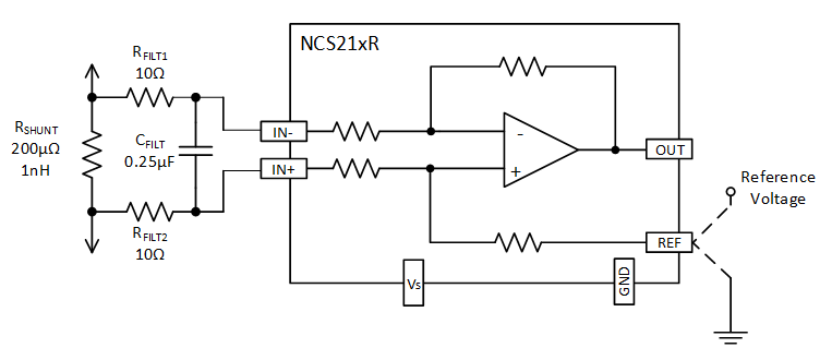
Other applications, such as DC-DC converter and power supply applications may also require filtering at the input of the current sense amplifier. Figure 1 shows the recommended schematic for input filtering.
Figure 1. Input filtering compensates for shunt inductance on shunts less than 1 mΩ, as well as high frequency noise in any application.
Input filtering is complicated by the fact that the added resistance of the filter resistors and the associated resistance mismatch between them can adversely affect gain, CMRR, and VOS.The effect on VOS is partly due to input bias currents as well. As a result, the value of the input resistors should be limited to 10 Ω or less. At a minimum, select the capacitor to exactly match the time constant of the shunt resistor and its inductance; alternatively, select the capacitor to provide a pole below that point.
To make the input filter time constant equal to or larger than the shunt and its inductance time constant:
This simplifies to determine the value of CFILT based on using 10 Ω resistors for each RFILT:
If the main purpose is to filter high frequency noise, the capacitor should be increased to a value that provides the desired filtering.
As an example, a filtering frequency of 100 kHz would require an 80 nF capacitor. The capacitor can have a low voltage rating, but should have good high frequency characteristics. The required capacitor value can be calculated by:
Transient Suppression
In applications that have transient common-mode voltages greater than 30 volts, transient suppression circuitry is required. Please refer to the Basic Connections application note within the NCS21xR datasheet for details on how to design a transient suppression circuit.
Filtering is not always required, battery powered DC circuits with minimal dynamic variations in current would be an example. Large, complex systems that can have high speed variations in supply current or voltage (e.g. servers, computing) often require filtering to provide clean signals for current control, measurement, and analysis.
For more information about ON Semiconductor's Current Sense Amplifiers please visit our website: